
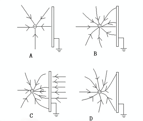
The shielding used in wire and cable products has two completely different concepts: electromagnetic shielding and electric field shielding. Electromagnetic shielding is designed to prevent cables transmitting high-frequency signals (such as RF cables and electronic cables) from causing external interference or to block external electromagnetic waves from interfering with cables that transmit weak currents (such as signal or measurement cables), as well as to reduce crosstalk between wires. Electric field shielding is designed to balance the strong electric field on the conductor surface or the insulation surface of medium- and high-voltage power cables.
1. Structure and Requirements of Electric Field Shielding Layers
The shielding of power cables includes conductor shielding, insulation shielding, and metallic shielding. According to relevant standards, cables with a rated voltage greater than 0.6/1kV should have a metallic shielding layer, which can be applied to each insulated core or to the multi-core stranded cable core. For XLPE-insulated cables with a rated voltage not less than 3.6/6kV and EPR thin-insulated cables with a rated voltage not less than 3.6/6kV (or thick-insulated cables with a rated voltage not less than 6/10kV), inner and outer semi-conductive shielding structures are also required.
(1) Conductor Shielding and Insulation Shielding
Conductor shielding (inner semi-conductive shielding) should be non-metallic, consisting of extruded semi-conductive material or a semi-conductive tape wrapped around the conductor followed by an extruded semi-conductive layer.
Insulation shielding (outer semi-conductive shielding) is a non-metallic semi-conductive layer extruded directly onto the outer surface of each insulated core, which can either be tightly bonded to or peelable from the insulation. The extruded inner and outer semi-conductive layers should be tightly bonded to the insulation, with smooth interfaces, no obvious strand marks, and no sharp edges, particles, scorch marks, or scratches. The resistivity before and after aging should not exceed 1000 Ω·m for the conductor shielding layer and 500 Ω·m for the insulation shielding layer.
The inner and outer semi-conductive shielding materials are made by mixing the corresponding insulation materials (such as cross-linked polyethylene, ethylene-propylene rubber, etc.) with carbon black, antioxidants, ethylene-vinyl acetate copolymer, and other additives. The carbon black particles should be uniformly dispersed within the polymer, without agglomeration or poor dispersion.

The thickness of the inner and outer semi-conductive shielding layers increases with the voltage level. Because the electric field strength on the insulation layer is higher inside and lower outside, the thickness of the semi-conductive shielding layers should also be greater inside than outside. In the past, the outer semi-conductive shielding was made slightly thicker than the inner to prevent scratches due to poor sag control or punctures caused by overly hard copper tapes. Now, with online automatic sag monitoring and annealed soft copper tapes, the inner semi-conductive shielding layer should be made slightly thicker or equal to the outer layer. For 6–10–35 kV cables, the inner layer thickness is generally 0.5–0.6–0.8 mm.
(2) Metallic Shielding
Cables with a rated voltage greater than 0.6/1kV should have a metallic shielding layer. The metallic shielding layer should be applied to each insulated core or cable core. Metallic shielding should consist of one or more metal tapes, metal braids, concentric layers of metal wires, or a combination of metal wires and metal tapes.
In Europe and other developed countries, due to the use of resistance-grounded double-circuit systems with higher short-circuit currents, copper wire shielding is commonly used. Some manufacturers embed copper wires into the separation sheath or outer sheath to reduce the cable diameter. In China, except for some key projects that use resistance-grounded double-circuit systems, most systems use arc-suppression coil-grounded single-circuit power supplies, which limit short-circuit current to a minimum, so copper tape shielding can be used. Cable factories process purchased hard copper tapes by slitting and annealing to achieve a certain elongation and tensile strength (too hard will scratch the insulation shielding layer, too soft will wrinkle) before use. Soft copper tapes should comply with GB/T11091-2005 Copper Tape for Cables.
Copper tape shielding should consist of one layer of overlapped soft copper tape or two layers of helically wrapped soft copper tape with gaps. The average overlap rate of the copper tape should be 15% of its width (nominal value), and the minimum overlap rate should not be less than 5%. The nominal thickness of copper tape should be at least 0.12 mm for single-core cables and at least 0.10 mm for multi-core cables. The minimum thickness of the copper tape should not be less than 90% of the nominal value. Depending on the outer diameter of the insulation shielding (≤25 mm or >25 mm), the copper tape width is usually 30–35 mm.
Copper wire shielding is made of helically wound soft copper wires, secured with a counter-helical wrapping of copper wires or copper tapes. Its resistance should meet the requirements of GB/T3956-2008 Conductors of Cables, and its nominal cross-sectional area should be determined according to fault current capacity. Copper wire shielding can be applied over the inner sheath of three-core cables or directly over the insulation, outer semi-conductive shielding layer, or an appropriate inner sheath of single-core cables. The average gap between adjacent copper wires should not exceed 4 mm. The average gap G is calculated using the formula:
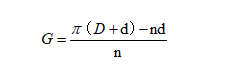
where:
D – diameter of the cable core under the copper wire shielding, in mm;
d – diameter of copper wire, in mm;
n – number of copper wires.
2. The Role of Shielding Layers and Their Relationship to Voltage Levels
(1) Role of Inner and Outer Semi-Conductive Shielding
Cable conductors are generally compacted from multiple stranded wires. During insulation extrusion, gaps, burrs, and other surface irregularities may exist between the conductor surface and the insulation layer, causing electric field concentration, leading to local air gap discharge and treeing discharge, and reducing dielectric performance. By extruding a layer of semi-conductive material (conductor shielding) over the conductor surface, it ensures tight contact with the insulation. Because the semi-conductive layer and the conductor are at the same potential, even if there are gaps between them, there will be no electric field action, thereby preventing partial discharges.
Similarly, there are gaps between the outer insulation surface and the metallic sheath (or metallic shielding), and the higher the voltage level, the more likely air gap discharge will occur. By extruding a semi-conductive layer (insulation shielding) on the outer insulation surface, an outer equipotential surface is formed with the metallic sheath, eliminating electric fields in the gaps and preventing partial discharges.
(2) Role of Metallic Shielding
The functions of metallic shielding include: carrying capacitive current under normal conditions, serving as a path for short-circuit current during faults; confining the electric field within the insulation (reducing external electromagnetic interference) and ensuring a uniform radial electric field; acting as the neutral line in three-phase four-wire systems to carry unbalanced current; and providing radial water-blocking protection.
Post time: Jul-28-2025